- Home
- Product
- Custom Cable Assemblies
- Applications
- Resources
- Blogs
- About Us
- Contact


 |
✓ Power + Signal in One Connector
2 main power contacts with 2 or 4 auxiliary contacts.
✓ XT 2+2 & XT 2+4 Options
Choose the configuration according to your required number of signal circuits.
✓ Custom Pin Assignment
Signal contacts can be configured for control, sensing, communication or other project-specific functions.
✓ Custom Power & Signal Wires
Wire gauge, material, color and cable length can be customized to your electrical requirements.
✓ Complete Custom Cable Assemblies
Available with branches, heat shrink, sleeving, terminals and custom opposite-end connectors.
✓ For Smart Battery, AGV, Robot & Energy Storage
Suitable for intelligent battery systems, BMS, AGV/AMR, robotics and industrial equipment.
✓ OEM / ODM Manufacturing Support
From drawing review and prototyping to testing and volume production.
Applications:
Smart Battery · BMS · Energy Storage · AGV / AMR · Robotics · Industrial Equipment
| Quantity: | |
|---|---|
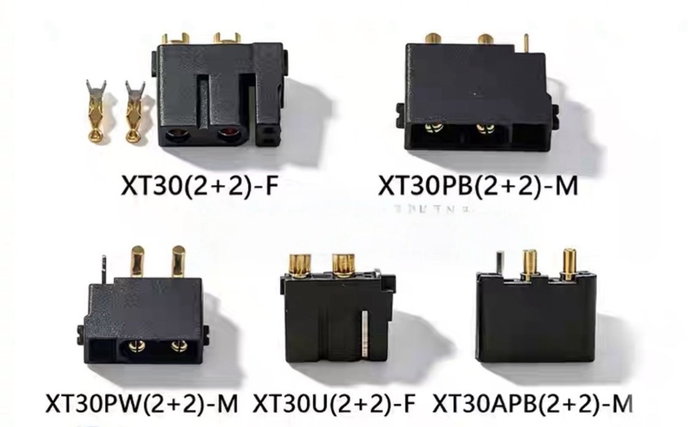
XT 2+2 and XT 2+4 hybrid power and signal connectors combine main power contacts and auxiliary contacts within a single interface. They are designed for battery-powered equipment that must transfer electrical power together with control, detection, communication or other low-current auxiliary circuits.
The XT 2+2 configuration generally combines two main power contacts with two auxiliary contacts. The XT 2+4 configuration combines two main power contacts with four auxiliary contacts, providing additional circuit capacity for equipment with more complex monitoring or control requirements.
By integrating power and auxiliary wiring into one connector, the hybrid design can reduce the number of separate interfaces, simplify cable routing and support more modular equipment assembly.
King Lai provides more than individual connector components. We develop complete OEM and ODM cable assemblies that integrate the selected XT connector, power wires, signal wires, pin assignments, branches, protective materials and equipment-side terminals into a ready-to-install wire harness.
Connector options: XT 2+2 and XT 2+4
Core function: Combined power and auxiliary circuit connection
Typical applications: Smart batteries, energy storage, AGVs, AMRs, robots and industrial equipment
Customization: Power wire, signal wire, AWG, pin assignment, cable length, branches and opposite-end connectors
The numbers describe the general contact arrangement of the hybrid connector.
XT 2+2: Two main power contacts plus two auxiliary contacts
XT 2+4: Two main power contacts plus four auxiliary contacts
The larger contacts are normally used for the main DC power path. The smaller contacts can be assigned to auxiliary circuits according to the equipment design.
Possible auxiliary functions may include:
Equipment control signals
Battery-status detection
Temperature-sensing circuits
Interlock circuits
Charging-status feedback
Communication lines
Equipment identification
Other project-specific low-current functions
The auxiliary contact function is not universally fixed. A four-contact auxiliary section should not automatically be assumed to support CAN, UART, BMS communication or temperature sensing. Every contact must be defined according to the approved connector datasheet, customer drawing and final pin assignment.
Comparison Item | XT 2+2 | XT 2+4 |
|---|---|---|
General contact structure | Two power contacts plus two auxiliary contacts | Two power contacts plus four auxiliary contacts |
Main purpose | Power with basic auxiliary circuits | Power with additional signal or control circuits |
Wiring complexity | Relatively simple | Supports more complex wiring |
Auxiliary circuit capacity | Two project-defined circuits | Four project-defined circuits |
Typical equipment | Smart batteries and compact electric devices | AGVs, robots, energy storage and smart equipment |
Wire-harness structure | Power wires plus two auxiliary wires | Power wires plus multiple auxiliary wires |
Main customization focus | Current, wire gauge and pin definition | Detailed pin assignment and power-signal integration |
Buyer benefit | Reduces unnecessary contacts and wiring | Integrates more equipment functions into one interface |
XT 2+2 is generally the more efficient option when the equipment requires only a limited number of auxiliary circuits.
XT 2+4 is more suitable when the device must integrate additional control, detection, feedback or communication connections.
The final choice should be based on the actual number of required circuits rather than selecting XT 2+4 simply because it has more contacts. Unused contacts can increase wiring complexity, connector size and project cost without creating additional value.
Feature | Engineering Advantage | Buyer Benefit |
Power and auxiliary contacts in one housing | Combines multiple electrical functions in one interface | Reduces the number of separate connectors |
Two main power contacts | Supports the primary DC power path | Creates a clear battery-to-equipment connection |
Two or four auxiliary contacts | Accommodates project-defined control and detection circuits | Supports smart and connected battery equipment |
Polarized connector design | Helps guide the correct mating direction | Reduces assembly errors |
Custom power-wire selection | Wire gauge can be matched to electrical load | Helps control voltage drop and temperature rise |
Custom signal-wire selection | Auxiliary wires can be matched to circuit requirements | Avoids unnecessary cable size and cost |
Defined pin assignment | Every wire and contact follows the approved drawing | Improves production consistency |
Power and signal branching | Different circuits can be routed to separate equipment interfaces | Simplifies internal device wiring |
Ready-to-install cable assembly | Connector, wire and terminals arrive as one assembly | Reduces customer-side processing and labor |
Prototype and production support | The design can be validated before mass production | Reduces development and launch risk |
Traditional battery equipment may use one connector for positive and negative power, followed by separate connectors for control, detection and communication circuits.
A typical traditional arrangement may include:
One main power connector
One signal connector
One temperature-sensor connector
One communication connector
Multiple wire branches and labels
This arrangement can work, but it may increase the number of components, assembly steps and potential connection errors.
A hybrid power and signal connector allows selected circuits to be consolidated into one interface.
Traditional Design | Hybrid Power and Signal Design |
Power and signal use separate connectors | Selected power and auxiliary circuits share one connector |
More individual components | Fewer separate connection points |
Multiple mating operations | More centralized installation |
More wire routing and labeling | Potentially simplified harness structure |
Separate connectors must be checked during maintenance | Key circuits can be managed through one interface |
Greater risk of connector mismatch | Polarized integrated design can improve error prevention |
The hybrid approach does not mean every system should use one connector for every function. Sensitive communication circuits, high-frequency signals, redundant safety circuits or waterproof connections may still require a separate interface.
The correct design is the one that balances electrical performance, installation space, serviceability, safety and total assembly cost.
XT30, XT60 and XT90 connectors are primarily selected for two-contact DC power transmission. XT 2+2 and XT 2+4 connectors add auxiliary contacts to support equipment that requires more than simple positive and negative power.
Comparison Item | XT30 / XT60 / XT90 | XT 2+2 / XT 2+4 |
Core positioning | High-current power connection | Combined power and auxiliary circuits |
Contact arrangement | Mainly two power contacts | Power contacts plus auxiliary contacts |
Main function | Transfers electrical power | Transfers power with additional circuits |
Harness complexity | Relatively simple | More detailed wiring and pin assignment |
Typical connection | Battery to ESC, motor or equipment | Battery to equipment with control or detection |
Typical applications | FPV, RC, drones and LiPo batteries | Smart batteries, AGVs, robots and energy storage |
OEM value | Customized power cable assembly | Integrated power and signal wire harness |
Choose XT30, XT60 or XT90 when the equipment requires a straightforward two-wire power connection.
Evaluate XT 2+2 or XT 2+4 when the equipment requires main power plus auxiliary circuits and the engineering team wants to reduce the number of separate connectors.
A conventional battery connection may require only:
Power positive
Power negative
A smart battery system can require additional circuits for equipment status, control, monitoring or communication.
A customized smart-battery harness may include:
Circuit | Possible Function |
Power positive | Main positive power path |
Power negative | Main negative power path |
Auxiliary contact 1 | Project-defined detection or control |
Auxiliary contact 2 | Project-defined feedback or communication |
Auxiliary contact 3 | Additional project-defined function |
Auxiliary contact 4 | Additional project-defined function |
The XT 2+2 configuration can support a battery system with a relatively simple auxiliary requirement.
XT 2+4 provides more flexibility when the battery must connect to several project-defined control, detection or communication circuits.
Fewer separate battery connectors
More centralized equipment connection
Easier module replacement
Clearer wire-harness standardization
Reduced final-assembly steps
Customized connection to the battery-management or equipment side
Improved consistency between prototype and production units
The connector should not be selected before the battery and equipment circuit definitions are complete. The engineering team must first identify the operating current, voltage, auxiliary functions, contact sequence and required safety circuits.
Energy storage equipment often combines battery modules, control electronics, monitoring devices and power-distribution components.
A hybrid connector can provide a centralized interface between:
Battery Module → Cable Assembly → Control or Equipment Interface
Potential energy-storage applications include:
Portable energy storage equipment
Modular battery packs
Battery cabinets
Backup power devices
Mobile energy systems
Industrial battery modules
Battery testing equipment
Replaceable power modules
Requirement | Hybrid Connector Value |
Main battery power | Larger power contacts support the main power path |
Status or control circuits | Auxiliary contacts support project-defined connections |
Modular installation | A centralized interface can simplify module replacement |
Maintenance | Fewer separate connectors may be easier to identify |
OEM production | Approved harnesses can be standardized |
Equipment integration | Opposite-end connectors can be customized |
The XT 2+2 or XT 2+4 connector is only one part of the energy-storage connection system. The cable gauge, insulation, operating temperature, contact rating, enclosure protection and safety requirements must all be reviewed before production.
Automated guided vehicles and autonomous mobile robots require battery power while also supporting control, charging, status feedback and system monitoring.
Possible XT 2+2 or XT 2+4 applications may include:
Removable battery modules
Internal battery-to-controller connections
Service-accessible battery harnesses
Power-distribution modules
Mobile robot battery interfaces
Low-speed logistics equipment
Industrial cleaning robots
Warehouse transport robots
Equipment Requirement | Cable Assembly Consideration |
Main battery load | Power contact and wire-gauge selection |
Peak motor current | Temperature-rise and voltage-drop evaluation |
Equipment status | Auxiliary contact definition |
Continuous vehicle movement | Wire flexibility and strain protection |
Vibration | Connector retention and cable support |
Maintenance access | Connector orientation and branch layout |
Repeated battery replacement | Mating-cycle and handling evaluation |
Charging system | Approved charging and interlock circuit design |
A standard XT hybrid connector should not automatically be treated as a dedicated AGV blind-mating charging connector.
Applications requiring automatic docking, large positional compensation, extremely high mating cycles, outdoor waterproof protection or very high charging current may require a specialized AGV charging interface.
Robots commonly contain several interconnected electrical systems:
Battery → Power Distribution → Controller → Motor → Sensor → Communication Device
Using separate connectors for every function may increase cable count, assembly time and maintenance complexity.
A customized XT hybrid connector assembly can combine selected power and auxiliary circuits for applications such as:
Mobile robots
Service robots
Inspection robots
Cleaning robots
Educational robots
Automated logistics equipment
Battery-powered industrial tools
Mobile automation platforms
Replaceable robot battery modules
Prototype autonomous equipment
More compact battery-interface design
Reduced connector count
Easier module installation
Customized cable routing
Improved wire identification
Consistent pin assignment
Integration with controller-side connectors
Lower customer-side assembly workload
Suitability should be confirmed according to current, voltage, vibration, movement, bend radius, mating frequency, operating temperature and required environmental protection.
King Lai can integrate XT 2+2 and XT 2+4 connectors into complete OEM and ODM cable assemblies based on customer drawings, samples or equipment requirements.
Custom Item | Available Direction |
Connector type | XT 2+2 or XT 2+4 |
Connector part number | Confirmed according to the selected manufacturer and version |
Connector gender | Equipment-side or battery-side configuration |
Power-wire gauge | Selected according to operating and peak current |
Power-wire material | Silicone wire, electronic wire or project-specified cable |
Signal-wire gauge | Selected according to the auxiliary circuit |
Signal-wire type | Standard, twisted, shielded or project-specified |
Pin assignment | Customized according to the approved wiring diagram |
Cable length | Customized for equipment layout |
Branch length | Individual lengths for power and signal branches |
Opposite-end connector | JST, Molex, circular connector, terminal or custom interface |
Terminal type | Ring terminal, blade terminal, crimp terminal or project-defined terminal |
Cable protection | Heat-shrink tubing, braided sleeving or protective conduit |
Strain relief | Customized according to movement and installation |
Identification | Labels, wire markers or color identification |
Packaging | Bulk or individually packed |
Production stage | Prototype, pilot run and volume production |
XT 2+4 connector → two larger-gauge power wires plus four auxiliary wires → divided branches → JST, Molex, terminals or equipment-specific connectors
This configuration allows the power conductors and auxiliary circuits to enter the equipment through one connector and then separate into the required internal interfaces.
The customer receives a complete wire harness rather than having to source the connector, power wire, signal wire, terminals and protective materials separately.
The words “XT 2+2” or “XT 2+4” are not a complete cable-assembly specification.
Before production, every contact must be clearly defined.
A pin-assignment document should specify:
Pin Information | Required Definition |
Power contact 1 | Polarity and connected wire |
Power contact 2 | Polarity and connected wire |
Auxiliary contact 1 | Circuit function and destination |
Auxiliary contact 2 | Circuit function and destination |
Auxiliary contact 3 | Circuit function and destination |
Auxiliary contact 4 | Circuit function and destination |
Wire color | Identification for each circuit |
Wire gauge | Conductor size for each contact |
Opposite-end position | Terminal or connector cavity |
Branch length | Distance from the main connector |
Shielding | Shield connection and termination method |
Testing requirement | Continuity, polarity or project-specific test |
Without a confirmed pin assignment, an assembly can appear physically correct while connecting the wrong circuits.
For this reason, King Lai recommends approving a drawing or golden sample before volume production.
List every circuit in addition to the positive and negative power connections.
Choose XT 2+2 when two auxiliary contacts are sufficient. Evaluate XT 2+4 when three or four auxiliary contacts are required.
Do not select a connector based only on the total number of contacts. Determine whether each auxiliary contact is used for detection, communication, control, feedback or another function.
The main power path must be evaluated for both normal operating current and temporary peak loads.
Motors, actuators and charging circuits may produce current levels that differ significantly from their normal operating conditions.
Power-wire size should be selected according to current, cable length, voltage-drop target, insulation rating and ambient temperature.
A larger connector cannot compensate for an undersized power wire.
Signal and auxiliary wires may use a smaller gauge than the power conductors, but their construction should match the actual circuit.
Shielding, twisting or specific insulation may be required for certain applications.
Confirm the connector orientation, cable exit direction, bend radius, branch positions and installation clearance.
Consider:
Temperature
Vibration
Dust
Moisture
Chemical exposure
Cable movement
Mating frequency
Required ingress protection
The connector, contacts, power wire, auxiliary wire, soldering or termination process and opposite-end connectors should be tested as one complete assembly.
The final current capability depends on the selected connector part number, contact construction, wire gauge, assembly process and operating environment.
Do not use the product name as the only current-rating reference.
Long cables, undersized wires and poor contact connections increase electrical resistance and voltage loss.
Auxiliary contacts are not automatically suitable for every communication protocol. Signal speed, shielding, grounding, interference and cable construction must be reviewed.
Some systems may require power, ground, interlock or communication contacts to connect in a specific sequence. Standard connector geometry may not provide the required first-mate or last-break function.
An auxiliary contact may be used as part of an interlock circuit, but the complete safety function must be designed and validated by the equipment manufacturer.
Standard hybrid connectors should not be assumed to provide a waterproof or dustproof rating. Environmental protection must be confirmed using the approved connector specification and final installation design.
Frequently replaced batteries or service-accessible modules may require higher mating-cycle durability than permanently installed internal wiring.
B2B customers usually require more than a standard connector. They need a repeatable cable assembly that matches the electrical design, mechanical layout and production process of the final equipment.
King Lai supports projects from initial requirement review through sample development and volume production.
Engineering support may include:
Connector and part-number confirmation
Power-contact and auxiliary-contact review
Pin-assignment preparation
Wire-gauge selection based on customer requirements
Cable-length and branch-layout review
Opposite-end connector integration
Drawing preparation
Prototype and golden-sample development
Production-process planning
Electrical and visual inspection requirements
Packaging and labeling definition
A complete drawing and approved sample help reduce misunderstandings during mass production.
King Lai has more than 30 years of experience in customized wire processing and connector assembly.
The company supports customized electronic cable and connector projects through standardized production procedures, engineering drawings, sample development and quality inspection.
Depending on the approved project specification, production controls may include:
Incoming-material verification
Connector and terminal confirmation
Wire-gauge and wire-color inspection
Cable cutting and stripping control
Crimping or soldering inspection
Pin-assignment verification
Polarity verification
Continuity testing
Short-circuit and open-circuit checking
Cable-length inspection
Branch-position inspection
Pull-force testing when required
Visual inspection
Label and packaging verification
Golden-sample approval before production
Applicable certifications, material declarations and testing documents should be confirmed according to the final connector, wire and assembly configuration.
To receive an accurate quotation, provide as much of the following information as possible:
XT 2+2 or XT 2+4
Complete connector manufacturer and part number
Connector gender
Operating voltage
Continuous operating current
Peak current and duration
Function of each auxiliary contact
Complete pin assignment
Power-wire gauge and material
Auxiliary-wire gauge and specification
Cable and branch lengths
Opposite-end connectors or terminals
Wire colors and identification requirements
Shielding or twisting requirements
Heat-shrink, sleeving or conduit requirements
Operating temperature
Vibration and movement conditions
Waterproof or environmental requirements
Drawing, photograph or reference sample
Prototype and estimated production quantities
If the final connector and wire specifications have not been selected, provide the equipment load, installation space and circuit requirements for engineering evaluation.
XT 2+2 generally refers to a hybrid connector with two main power contacts and two auxiliary contacts. The exact contact rating and auxiliary functions depend on the selected connector part number and project design.
XT 2+4 generally combines two main power contacts with four auxiliary contacts. It is suitable for equipment requiring more auxiliary circuits than the XT 2+2 configuration.
Not necessarily. They may be assigned to control, detection, feedback, communication or other low-current circuits. Their functions must be defined by the equipment designer.
XT60 is primarily a two-contact power connector. XT 2+4 combines two main power contacts with four auxiliary contacts, allowing power and selected additional circuits to share one interface.
It can be evaluated when the battery requires main power plus additional control, monitoring or communication circuits. The final connector, pin assignment and electrical ratings must match the battery and equipment design.
They can be evaluated for battery modules, portable energy-storage devices and other systems requiring power plus auxiliary circuits. Electrical load, safety and environmental requirements must be confirmed.
They may be suitable for internal battery and equipment connections. They should not automatically be treated as dedicated blind-mating AGV charging connectors.
Yes. The main power conductors are normally selected according to electrical load, while auxiliary wires can be selected according to their circuit requirements.
Yes. Power and auxiliary wires can be divided into customized branches with different lengths and opposite-end interfaces.
Yes. King Lai can integrate the XT connector, power wires, auxiliary wires, pin assignment, branches, terminals, protection and labeling into a complete OEM or ODM cable assembly.
Prototype and sample development can be arranged based on drawings, specifications or reference samples. A confirmed drawing and approved sample are recommended before volume production.
The complete connector part number, operating current, power-wire gauge, auxiliary-contact functions, pin assignment, cable length, opposite-end connectors and estimated quantity are the most important starting points.
Request a Custom Hybrid Connector Cable AssemblyNeed to integrate power, control and auxiliary circuits into one equipment-ready wire harness? Send King Lai your connector part number, pin assignment, operating current, wire specifications, cable lengths, opposite-end interfaces and estimated quantity. Our team will review your requirements and help develop an XT 2+2 or XT 2+4 cable assembly for prototype validation and volume production. |